I put the pieces of the cart together as shown here:

Next step was the wheel assembly. I needed 1" #6 bolts to put the 3 pieces together (each piece is 1/4"). Once I got it together I realized that it was upside down (the holes for the axle needed to be on the bottom), so took it all apart and reassembled.
Next was the driving wheel. The pre-drilled holes in the mounting wheel were not big enough for any screws I had or could get quickly, so I reamed them and used #4 sheet metal screws (needed 1/2"--another shopping trip). Pan head screws won't do because the wheel needs to clear the motor. Even with flat-head screws I had to file down a small plastic cylinder on the motor, which has no use that I can discern.
Now I was ready to mount the motor. I was clueless here, but I thought ahead enough to buy a mounting bracket, which attaches to the motor with a #4 machine screw (again, 1/2" flat-head). I measured the cylindrical piece to the motor--it's 3/4". I drilled a 3/4" hole in the ABS side (3/4" from the bottom like the other wheels, and over enough so that the wheel did not extend beyond the front of the body--2.25" in). I had to file the hole to get the motor through it, but it's in and stays put. The bracket doesn't do much, but if I need to secure the motor later on, I can screw it to a piece of plywood that I secure to the frame.
The motor is a Solarbotics GM2 Offset Shaft Gear Motor. I used a Solarbotics GMW mounting wheel, and GMB28 Mounting Bracket.
Next was the limit switches. They need to be in the front with the sensors out so that when they hit something the switch will activate the timer sequence and flop the relay for 5 seconds, reversing the motor. (See my post, including a video, on the circuit.) I drilled the holes (1/8") on both sides but only mounted one, using 3/4" #4 machine screws and nuts. I'm keeping the other connected to the breadboard circuit for the final pre-completion test.
Next Steps:
- test the circuit again
- construct the circuit on an +Adafruit Industries Perma Proto Board and mount it on standoffs in an Altoids Tin with insulation on the bottom
- test and rework as necessary
- solder everything up and go
Here's what it looks like at this point:
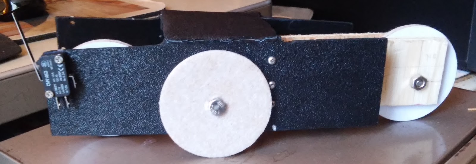 |
| Right view. Note the limit switch on the front. |
 |
| Front view (driving wheel, motor. limit switch) |
 |
| Rear view (moveable wheel assembly, hinge) |
 |
| Left view (motor protruding through hole) |
No comments:
Post a Comment