Getting past the fact that the 555 won't supply enough voltage, ever, the next question is how can we amplify it. The answer is with a transistor. It took me way longer than it should have to get it to work, because of wiring problems and cooked transistors.
First the wiring: instead of taking 555 Output Pin 3 to the + side of the relay coil, I connected it to the base pin of a 2N2222A transistor (NPN BJT). I then connected + side the relay coil to the 5V rail, and the - side of the coil to the collector pin of the transistor. The emitter pin goes to GND. Initially, I left the LED in the circuit, but since that's connected to GND, the circuit was always completed. I'm sure there's a place I can put it, but it works without it.
After few wrong connections, I still could not get it to work. I was absolutely sure that it was wired correctly. During this process I must have cooked a transistor or two, In desperation, I replaced the transistor again, and it worked.
So, that's the answer: insert a transistor, properly wired, and the voltage that was too low to trip the relay is enough to activate the transistor, allowing 5V to flow from the 5V rail through the relay to the collector, and when the 555 is triggered, the output pin will supply enough voltage to the base pin of the transistor to allow current to flow through to the emitter, completing the circuit.
Here's the video
I'm glad I got this to work. I hate to leave something incomplete..
Showing posts with label 74HC04. Show all posts
Showing posts with label 74HC04. Show all posts
Sunday, March 15, 2015

Friday, March 13, 2015
@MAKE Electronics Experiment 20: Keypad Security System (Part III--still not working)
This has taken a while. Snow, family visiting, setting up my new generator, an fuel oil spill in my basement, and other events have dominated my attention.
When last we left this, I was convinced that the keypad was sucking current from the circuit. I used this one. The only videos I've seen of people getting this to work use momentary buttons instead of the keypad, I tried to substitute buttons--that didn't help. Testing various locations with my meter, I see that's not the problem
I checked the voltage coming into the first part of the circuit, and then then through the operation. I put a meter set to continuity connected to the relay. If the upper coil on the relay gets 5V, there should be continuity, and 5V to the lower coil should reset it. As you can see in the video, holding the '*' key and entering the code causes the indicator light to turn on for ~1s as designed, but the relay does not flop. The voltage meter shows <4V coming out of the 555--not enough for the relay. If I hit the relay with a jumper wire connected to the 5V rail, the relay flops and there is continuity until I press the '#' key or hit the lower coil with 5V,
Testing various locations with my meter, I see that's not the problem. Here's the video.
The 555 has 4.86V going in on pin 8 and only ~3.7 going out on pin 3. That's the problem, and I don't know what to do about it. I fussed with capacitor and resistor values with no change. For the video, I wound up with ad 1000uf capacitor and a 10K resistor, so pin 3 would have output for longer and I could see it on the meter. I tried various combinations of 2.2, 10, 100, and 1000uf capacitors and 1K, 10K, and 100K resistors--the output stayed under 4V.
Researching, I found this web page, which says that the output on pin 3 will be ~1.7V less than the input on pin 8. Charles' Encyclopedia of Electronic Components Volume 2 says the same thing. I'm going to move on.
When last we left this, I was convinced that the keypad was sucking current from the circuit. I used this one. The only videos I've seen of people getting this to work use momentary buttons instead of the keypad, I tried to substitute buttons--that didn't help. Testing various locations with my meter, I see that's not the problem
I checked the voltage coming into the first part of the circuit, and then then through the operation. I put a meter set to continuity connected to the relay. If the upper coil on the relay gets 5V, there should be continuity, and 5V to the lower coil should reset it. As you can see in the video, holding the '*' key and entering the code causes the indicator light to turn on for ~1s as designed, but the relay does not flop. The voltage meter shows <4V coming out of the 555--not enough for the relay. If I hit the relay with a jumper wire connected to the 5V rail, the relay flops and there is continuity until I press the '#' key or hit the lower coil with 5V,
Testing various locations with my meter, I see that's not the problem. Here's the video.
The 555 has 4.86V going in on pin 8 and only ~3.7 going out on pin 3. That's the problem, and I don't know what to do about it. I fussed with capacitor and resistor values with no change. For the video, I wound up with ad 1000uf capacitor and a 10K resistor, so pin 3 would have output for longer and I could see it on the meter. I tried various combinations of 2.2, 10, 100, and 1000uf capacitors and 1K, 10K, and 100K resistors--the output stayed under 4V.
Researching, I found this web page, which says that the output on pin 3 will be ~1.7V less than the input on pin 8. Charles' Encyclopedia of Electronic Components Volume 2 says the same thing. I'm going to move on.
Wednesday, February 18, 2015
@MAKE Electronics Experiment 20: Keypad Security System (Part I)
Experiment 20 builds on the logic chip exercise in #19 to build a keypad security system. The full experiment ends with hacking into a computer's power button and cutting a hole in the case to attach the keypad. I have several carcasses around that I can use for that, but I think rather than dedicating the system to a computer I don't use I will do the experiment with the case open. I will go as far as cutting the power lines and fixing them to the relay.
That's getting a little ahead of where I am. Here's the project:
Use a 12-button keypad (like a telephone) with 14 contacts (1 for power, 1 for each of the 12 buttons, and 1 dummy) to enter a 3-digit security code in order to be able to power on a computer. The circuit is connected to the power-on button in the computer, which therefore won't work unless the code has been entered.
The contacts for the 3 digits used for the code are connected to 3 of the 4 AND gates in a 74HC08:


That's getting a little ahead of where I am. Here's the project:
Use a 12-button keypad (like a telephone) with 14 contacts (1 for power, 1 for each of the 12 buttons, and 1 dummy) to enter a 3-digit security code in order to be able to power on a computer. The circuit is connected to the power-on button in the computer, which therefore won't work unless the code has been entered.
The contacts for the 3 digits used for the code are connected to 3 of the 4 AND gates in a 74HC08:
- Gate1 input1 is connected to digit 1 of the code, a 10K pull-down resistor, and GND. Input2 is connected to the input of Gate1 of the 74HC04 inverter, a 10K pull-down resistor, and GND.
The output is connected to input2 of AND Gate2, and also through a diode back to Gate1 input1.
So, Gate 1 input 2 is always HIGH, since the inverter input is always LOW. When the digit is pressed, input1 goes HIGH and stays there due to the diode for latching (see experiment 19). H/H ANDS to H, so input 2 of Gate 2 is H only when digit1 has been pressed. - Gate2 input1 is connected in the exact same configuration as Gate1: 10K resistor and GND, also a diode and gate2 output. Thus, if digit1 has been pushed, input2 is H and if digit 2 is then pushed input1 is H, making output H and latching there.
Output2 goes to Gate3 input 2 as well as back through the latch. - Gate 3 input 1 is connected to a pull-down resistor and GND and to digit3 (no latch). So only if the first two digits have been entered successfully, input 2 is H, and when digit3 is pressed the output3 is H.
Output3 (Gate3 output) goes to Inverter Gate2 input.
Inverter Gate2 output goes to pin2 (trigger) of a 555 timer. H output of AND Gate3 is inverted to L, triggering the timer.
- 555 pin3 (output) is connected to an LED==>10K resistor==>GND and also to the upper coil of the latching relay
- So, when the 555 is triggered, the positive pulse flashes the LED and activates the relay, completing the power circuit inside the computer and allowing the computer to be powered on.
Two other keys of the keypad (* and #) are also in use:
- The * key powers on the circuit, while it is held down. I connects to an LED/resistor/GND to show that power is on, and to the power pins of the ICs (pin 14 of the logic chips, pint 8 of the 555). It also connects through a 100K resistor to pin 7 (discharge pin) of the 555.
- The # key connects to the lower coil on the relay, as well as to an LED/Resistor/GND. So when the button is pushed, the LED lights, and the relay unlatches, disabling the power on the computer
- So, to start the process, press the * key and hold it while entering the 3 digit code, in sequence. LED1 is on while the key is held. LED 2 flashes when the relay is activated. The * key can then be released, and the computer can be powered on. After the computer is powered down, the # key deactivates the relay and it can not be turrned back on again until the code is reentered.
The 555 serves to send a pulse to activate the relay. In addition to the connections already discussed, pin 8 connects to pin 4 (reset), to keep it H while the * button is held. Pin 7 also connects to pin 6 (threshold), Pin 6 also connects to a 10uf capacitor and GND. Pin 5 (control, connects to a .1uf capactor and GND). Pin 3 (output) connects to an LED/resistor/GND in addition to the upper coil on the latch, so it flashes the LED when the 555 is triggered.
Here's the schematic from figure 4-84 on p. 201 of the book:
Here's what I've done on the breadboard so far (a little messy):
I'll post another when I' closer, but it represents the schematic less the keypad.
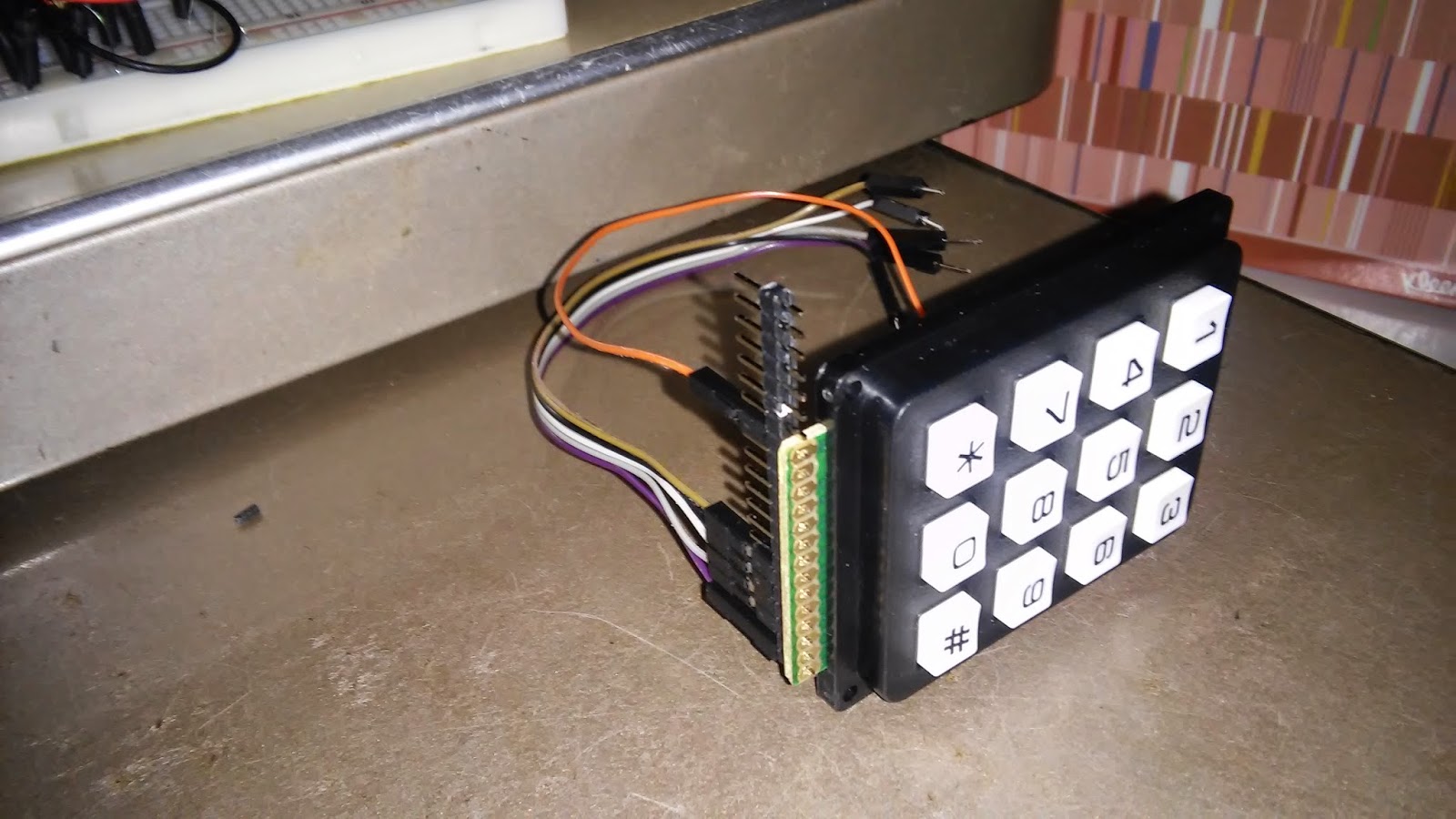
For the keypad, I'm considering soldering a set of header pins, so I can either stick it directly in the breadboard or use F/M jumper wires as depicted below. The top wire is power, The others are randomly connected for now, but they will go to the pads assigned to numbers as discussed above. Other options are to solder wires directly to the pads or to use female headers.
More when I get to soldering.
Subscribe to:
Posts (Atom)


