Showing posts with label electronics. Show all posts

Friday, December 22, 2017

Ham Shack Major Upgrade


This is my little corner of the world. The new desk is almost finished. Key features:
  1. about 7ft wide, 30" deep and 7ft high
  2. 3 drawers on the left, room for 2 computers plus paraphernalia (UPS, ethernet switch, etc) on the right--I will add the second computer after I install AndysHamV21 on it
  3. ~18" adjustable shelves on each side
  4. top shelf holding misc items
  5. middle shelf for stability and storage--and ultimately my on air sign 
  6. 200mm computer case fan to cool the HF rig (Ten Tec Jupiter)
  7. small, fixed shelf on the right to hold the 2M rig and power supply
  8. my DIY 12V power strip (for the fan and sign)
  9. pull-out keyboard shelf and pull out work/writing area
  10. 8-outlet power strip (behid the monitors and radio)
  11. 26" Samsung TV/monitor connected via HDMI cable
  12. 21"  monitor connected via VGA cable through a KVM switch to both computers to facilitate sharing
  13. pre-existing telephone jack now comes in through a wall plate in the desk side
  14. 2" holes in several locations for wire management
  15. notches in each of the 18" shelves to accommodate wires and cables
It took the equivalent of 4 4'x8' sheets of 3/4" plywood, plus some 2x4s for framing, some 1"x4" pine for trim, and some 1/2" plywood for the keyboard shelf. I put on 2 coats of stain plus 2 coats of polyurethane (8 coats on the desktop). We  used drawer slides from Rockler for the drawers and the pullouts

We also took the time to run the coax from the 2M and HF antennae across the ceiling and behind the wall. The desk is where the coax came into the shack anyway--it's just neater now, coming in through a wall plate and on to the radios,. We also ran the ethernet cables behind the walls. There had been cables all over the place. Now the ethernet runs:
  • from the cable modem/wireless router into the wall across the ceiling to a dual wall plate
  • from the dual wall plate an ethernet switch
  • from the switch to the XYL's computer and another cable from the switch back into the wall plate
  • from the wall plate across the ceiling to another wall plate under the desk
  • from the wall plate to another switch that feeds each computer
Dual ethernet wall plate--cable comes from the cable modem/wireless router and into switch. One output from the switch goes to the XYL's desktop--the other goes back to the wall plate and on to the shack

I'm in heaven.  All credit goes to my brother-in law (the one with the skills). .This is a substantial piece of furniture. I can't get a clear shot to take a photo of the whole thing--it's too big. I still have a little work to do, but it's great!

Wednesday, December 13, 2017

12V DC Power Strip

Assembled and tested, ready for use

I have been busy with some projects lately, and have not been active on the blog. This effort is a small part of my desk project that will be on the blog soon (give or take...).  The desk will accommodate (among other things) my amateur radio equipment.  Amateur radio stuff generally runs off ~12V DC (actually closer to 13.8). There are DC power strips available commercially, but because they handle 30 Amps or more and are intended to be fed by a power supply designed for a radio, they are expensive. I just want to power a fan that cools the radio and a station "on air" sign, so I don't need that.

So, I got a Harbor Freight givaway 110VAC power strip, and took it apart.

I cut off the power cord (it will make an extension cord someday), removed the safety ground copper strip, and drilled out the slots for the prongs of AC plugs to accommodate DC binding posts.
Strip with holes drilled, and some posts installed. Note the mod to the red post on the right.
I cut off the threaded bottom parts to leave just the post (see photo).  Then I soldered the bare binding posts to the copper strips on the positive and negative rails, and screwed bottom back on.
Next I needed a 12V supply. I bought an old wall wart for US$2 at a "Hamfest" (that's basically a flea market for amateur radio people, although there can be some high priced stuff there). Since the jack on the wall wart was not standard, I cut it off and just soldered the wires to the wires to the power strip. It will handle 1250mA, which should be sufficient. As shown in the first photo, it worked. Next step: plug the 200mm computer case fan into the power strip.

Fan plugged into power strip
I'll add the On Air sign after Santa Claus brings it.

Preview of the desk. The blue light to the right of the monitor and behind the radio is the fan--it has 4 blues LEDs, powered by the wall wart through the power strip. My old desk is on the left. It will be removed soon.
I've been using the desk, although we have a couple of additions to make.  We'll add a slide-out drawer for the keyboard and mouse, and a pull-out work surface on the right, over the computers. We also have some trim to add. When I say "we" I mean my brother-in-law--the one with the skills--under my "supervision."

Thursday, August 27, 2015

@MAKE #Electronics Experiment 32: Robot Cart (Part III - Cart is together)

The saga continues...

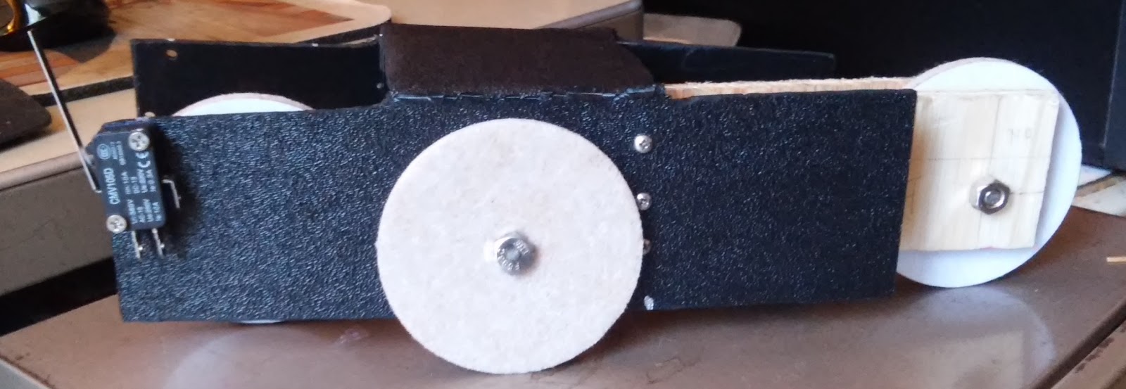
I put the pieces of the cart together as shown here:
I attached the hinge to the body only to expand the pilot holes to make it easier when I put the movable wheel assembly together (see upper right).  The wheel at the lower right has the mounting wheel for the motor ready to go.

Next step was the wheel assembly.  I needed 1" #6 bolts to put the 3 pieces together (each piece is 1/4").  Once I got it together I realized that it was upside down (the holes for the axle needed to be on the bottom), so took it all apart and reassembled.

Next was the driving wheel. The pre-drilled holes in the mounting wheel were not big enough for any screws I had or could get quickly, so I reamed them and used #4 sheet metal screws (needed 1/2"--another shopping trip).  Pan head screws won't do because the wheel needs to clear the motor. Even with flat-head screws I had to file down a small plastic cylinder on the motor, which has no use that I can discern.

Now I was ready to mount the motor. I was clueless here, but I thought ahead enough to buy a mounting bracket, which attaches to the motor with a #4 machine screw (again, 1/2" flat-head). I measured the cylindrical piece to the motor--it's 3/4". I drilled a 3/4" hole in the ABS side (3/4" from the bottom like the other wheels, and over enough so that the wheel did not extend beyond the front of the body--2.25" in). I had to file the hole to get the motor through it, but it's in and stays put. The bracket doesn't do much, but if I need to secure the motor later on, I can screw it to a piece of plywood that I secure to the frame.

The motor is a Solarbotics GM2 Offset Shaft Gear Motor. I used a Solarbotics GMW mounting wheel, and GMB28 Mounting Bracket.

Next was the limit switches.  They need to be in the front with the sensors out so that when they hit something the switch will activate the timer sequence and flop the relay for 5 seconds, reversing the motor. (See my post, including a video, on the circuit.) I drilled the holes (1/8") on both sides but only mounted one, using 3/4" #4 machine screws and nuts.  I'm keeping the other connected to the breadboard circuit for the final pre-completion test.

Next Steps:

  • test the circuit again
  • construct the circuit on an +Adafruit Industries Perma Proto Board and mount it on standoffs in an Altoids Tin with insulation on the bottom
  • test and rework as necessary
  • solder everything up and go


Here's what it looks like at this point:
Right view. Note the limit switch on the front.
Front view (driving wheel, motor. limit switch)


Rear view (moveable wheel assembly, hinge)

Left view (motor protruding through hole)


Monday, August 24, 2015

+Adafruit Neopixel Tiara on an Actual Tiara- Almost Built

Design change:  I have ruled out the CR1220's (not enough battery life, too hard to change), and the CR2032's (too bulky). +Becky Stern  was trying to push me towards a LiPo battery, and I resisted...but finally realized she is right. The 100mAh version is small and the right size to fit the tiara.

I sewed eacghneopixel to the tiara using silver
thread.  Here's the first, ready to go..
The "V2" on the back side happens to be on the
"data-in" pin, so I started there with each one.
Here's the tiara with pixels shown. I'm still have to clean up the stray threads.
The sewing took me an afternoon (not an expert), but I got it done and it's not too ugly.

Next I soldered the neopixels together (+ to +, - to -, DO to DI), then connected the Gemma to the first neopixel for a test, using alligator test leads--see the video. The soldering took a couple of hours. For each wire, I used calipers to measure the distance between neopixel pads, stripped 14", marked the desired length of unstripped wire (from the calipers), cut the wire 1/4" beyond, and stripped 1/4" off that end.

I did the data bus first, and used stranded wire.  That turned out to be a huge pain--it's too flexible and the ends are hard to deal with.  I switched to 22awg solid core wire for the power and GND busses. Much easier.  I will go back to stranded when I wire the Gemma, because I will need the flexibility.

Also, I discovered (or remembered, not sure which) that Gemma has an on-off switch on board.  That simplifies this circuit (I don't need to add a switch).

Next:

  • trim stray threads and wire to clean up as much as possible
  • re-sew at least one of the neopixels (some threads got burned during soldering)
  • secure and insulate the threads and wires with nail polish
  • add the 100mAh battery
  • glue the Gemma to the tiara
  • solder the Gemma connections to the circuit, attach the battery to the tiara.


Parts list:

Saturday, August 22, 2015

@MAKE #Electronics Experiment 32: Robot Cart (Part IIA-Better)

3rd attempt at the cart.  Used a hand saw this time, and my handy drill. I marked Xs on the pieces I want to cut out to remind me what I'm doing.

Cart is now fabricted.  You can see some damage from bending the frame, but it will do for now.  I may redo it if I like the final product and want to showcase it.
OK, so I can't follow directions. It's a good thing I bought 10 sheets of ABS, because I have ruined 2 now, and may need another.  I got through my measuring, drilling and cutting, only to see that I pu the cuts on the wrong side.  So, I measured and drilled again...that's the top photo..and took the step to mark the pieces that wanted to cut out.

I made the cuts. used my heat gun to soften the plastic, and bent the sides.  I left the final cuts (removing the short pieces on what would become the top) so I could bend those into a position to cut them.  It was ugly.

I'd like to say that I started on the wrong side on purpose (one side is textured and the other smooth), but it was by mistake. It turned out to be almost OK because I had significant shaping and deburring to do, using my Harbor Freight Dremelish tool.

When I bent the frame back to put the textured side out, there was some damage (see lower photo).  It's usable as-is, so I'm going with it.  If I really like the cart when it's done. I'll redo the frame.

Next:
By some 14" plywood, the hardware (hinge, bolts, nuts, screws), and maybe some 3" disks to use as wheels,  as suggested by James Floyd Kelly.

Friday, August 21, 2015

@MAKE #Electronics Experiment 32: Robot Cart (Part II)


So, carpentry and fabrication are not my strong suits. Evidently I'm not real strong on following directions, either. Anyway, this is pass one, and I'll keep at it.

The good news:  I proved that I can use the 12"x12"x1/8" sheets of ABS (that I bought from Amazon about a year a go thinking they's come in handy) for the main cart body.  They're not thick enough to screw into, so I'll add 1/4" plywood, or maybe see if I can find 1/4" ABS.  I was able to cut the sheet to 9"x8", drill holes for rounding corners, then cut the rest, and use my heat gun to soften it for bending into shape See Fig. 5-92 on p. 275.

Problems:
  1. I used the wrong saw. That's why the cuts look ugly.  I knew that, but I bought a reciprocating saw at Harbor Freight and have been dying to use it.  I'm going to a hand saw, maybe a coping saw. 
  2. I drilled 3 of the holes in the wrong place. The idea is to have 1/2" diameter holes to round the 4 corners of the cut ABS, but you need to drill the holes in the inside of the cut, not the outside (that's why you see some holes that don't appear to be random--they are just wrong).
Other than that it's great.  I'm ready for pass two, and I learned a lot.

Tuesday, August 18, 2015

@MAKE #Electronics Experiment 32: Robot Cart

I'm ready to start on this. First step was to gather the materials.  The parts list on page 268 is incomplete, although on p. 276 there's a "you will also need..." See the schematic on p.277 and this blog post by +James Floyd Kelly  (it's on experiment 31, but references shopping for 32). The 50K potentiometer shown in the schematic controls the time the motor runs in reverse before going forward again.
Make: Electronics by Charles Platt, Figure 5-98. p.277 (in the edition I have)

Also, the erratum on p. 277 mentions adding a diode or transistor. I'm going to try a diode (handsonelectronics says diode).

I found that my DPDT relays on hand are not appropriate. Some are latching relays bought for experiment 20, and the other was 12V, so I ordered two 5V DPDT non-latching relays from Amazon.

Charles spends a great deal of time on fabrication and not much on the circuit.  Since I care more about the circuit, and there are some issues with it, I'm going to build that first. I'm going to try to use plastic for fabrication. I have some 12"X12" pieces of ABS, and the shell of a multi-function printer that I tore-down.

Here's the concept:
When switched on, the cart moves forward until one of the microswitches hits something, it cuts power to 555 Trigger Pin 2, causing the the Output Pin 3 to pulse the relay, which then flops, reversing voltage to the motor, which reverses. The timer cycle (determined by 555 Threshold Pin 6 and Discharge Pin 7 as powered by the capacitor/resistor combination along with the Pot). When the cycle ends, the Output Pin 3 goes low and the relay flops back, causing the motor to reverse again (making it go forward).

The time it reverses starts at ~5 seconds (47uf cap*100000Ohm resistor = 47//1000000*100000 = 4.7). The Pot did not make much difference, if any. I thought it did, but it turned out that I had unhooked the 100K resistor. DUH.

I had other DUH moments in this, but I was helped immeasurably but people running into the same problems I did, particularly +James Floyd Kelly .  Thank you James. First, I bought a 5V gearmotor from robotshop .com. I fussed around for way too long trying to figure out how to wire it--then I noticed the two copper tabs on the neck.  Second, I was getting weird buzzing from the relay, and the motor was not reversing. I remember the symptoms from James' blog. My relay had different pinouts from the schematic. There are 8 pins. If you number them 1-8 starting with 1 at upper left and go counter clock-wise, I needed to switch pins 2 and 3 on one side and 7 and 6 on the other.  I could not find a datasheet for this relay, but I had a similar issue once before with another DPDT relay, so I guessed.

Third problem was the diode,  The motor would not reverse, but fortunately I had seen this before (thanks James), so I added the diode across pins 1 and 8 of the relay with the cathode towards pin 8.

I also struggled with wiring the switches.  I tested it with just the switches, power supply, and a meter, and came up with:
555 Trigger Pin 2  to switch1 NO prong, connected to switch 2 NO
Both NC Prongs connected to GND
Both COM prongs (on the side--at least on mine) connected to GND

If neither switch is pressed, current is flowing to the trigger pin through the 10K pull-up resistor making it high and thus the output pin is low. When either switch is pressed, the trigger pin goes low, making the output pin high, and flopping the relay and reversing then motor.  The output pin stays high until the 47uf capacitor dishcarges (4.7sec) to the threshold pin, making it high and setting the output pin back to low, flopping the relay back and the moving the motor in the original direction.

It works.  Here's the video.

Tuesday, August 11, 2015

@MAKE #Electronics Experiment 31: One Radio, No Solder, No Power with thanks to @sqfield (+Simon Field)

This is one of those things I've wanted to do for over 55 years.  If I'd only had more motivation and more support, I would have.  Water under the bridge, so here's my attempt now.

First of all, contrary to Charles' title, there was solder: I was too aggressive with my stripping to create the tapes in the coil, and cut the wire, so I had to solder the two pieces together and add some heat shrink for insulation.


Parts ready for assembly: coil with taps ever 50in, wrapped around vitamin bottle, spool of solid core 22awg hookup wire for ground--40ft left after the coil, germanium diode (on top of the white spool), 100ft og 16awg stranded wire for antenna, piezoelectric earphone, hose clamp to connect ground wire to water pipe. The earphone I bought (from SciToys) has a plug on the end, so I bought a jack for it from Radio Shack and connect the ground and earphone wires to it.

This is +charles platt 's experiment, but he directs the reader to scitoys.com for parts. This website, run by +Simon Field, has a wealth of fun projects.

Before adding the coil and the antenna, I tried a couple of suggestions from SciToys. First, I touched one end of the diode to a water pipe for ground and the other to the ground contact on the phono jack. I held the audio input (left, because it's a stereo jack and the left is where the contact on the mono earphone is) to use my body as an antenna. Got nothing.  Next, I taped the hookup wire to the water pipe and cut off a length of wire that would allow me sit in a chair on my patio, and connected that to the ground on the jack with an alligator clip.  I connected one end of the diode to audio input and held the other end, again being the antenna. Still nothing.

There is an AM tower within about 3 miles, so I think I should be able to get something. Next, I tried adding the coil and the 16awg antienna.  There is lightning in the area for the next couple of days, so I stayed inside: I ran about 60-70ft of wire up the basement stairs through the living room and around the family room. Then, I went back to my basement workshop and assembled what you see in the photo below.
The black and red wires at the bottom go to the water pipe and upstairs.  The green alligator clip lead goes from ground on the jack to the taps on the coil. The red alligator clip lead goes from the diode to audio input on the jack. The paper clip hanging from the tap (upper left) marks where I heard something.
When the weather clears I'll try the antenna outside, but here's what I got:

  • I heard static right away in the earphone
  • When I moved from tap to tap, the static went away--silence
  • At one pint, on one tap, I heard some Spanish--SUCCESS! I couldn't get it back, but I'm happy
I will post again after I move outside. I have some other components too, like a variable capacitor and a coil+ferrite rod, so I will plan adding those while I'm waiting for the weather to clear.


Tuesday, July 28, 2015

LG W2243T-PF Monitor (NOT) Fixed

Position of capacitors on the power board
From this ebay listing
This was going to be a success story.  My monitor went dark (well, it just flashes the LG logo, then the display, then goes dark--it does with 2 computers).  This was actually a refurbished model that LG sent me to replace another (different model) that went dark about 3 years ago.  This one was originally manufactured in 2009, according to the sticker on the device.

This repair is something I never would have considered until I began my electronics hobby at Christmas 2013.  I didn't even know how to solder until a few months after that. Now, after numerous blinking light and other educational projects (see the rest of this blog), I had the opportunity to do something useful.

Unfortunately, this repair did not do the trick--so either something else is wrong. or I did not fix it properly (I think the former, because there is no change in the monitor's behavior, but I'm perfectly willing to accept blame.  But this was educational, and only cost me about 50 cents US in parts to apply.

I was aware that faulty capacitors were probably the cause, so I found the ebay listing above, for a "repair kit" and a couple of YouTube videos.  The ones where it all goes smoothly are not very useful, because things rarely go smoothly.  I found one where the author struggled to get the case open and that's the real challenge. Find it here. I killed my fingers, as the author indicated, and the final push required the gentle insertion and twisting of a screwdriver, but I got it open.

Note: the author of that video only wanted to remove the stand.  To someone remove the capacitors after having an easier time opening then monitor, try this one.

Once it was open, the rest was fairly straightforward.  I marked the location of the wires I disconnected, and removed the housing, which was taped on. I was then able to remove the circuit board for the power supply (4 screws), turn it over, and see that some of the capacitors were bulging, showing signs of stress. Since I had appropriate replacement capacitors in the 125 assortment in  this kit on ebay, which cost about the same as the repair it, which only had 6 capacitors (so I still have some subset of the 119 remaining capacitors).
Open, turned over, housing marked to id wires for replacement
Housing opened and turned over
Circuit board removed. Note bulges on some capacitors

The capacitors on the board were 1000uf 16V and 470uf 35V, all 105 degrees C.  Mine were the same, except that the 470ufs were 50V.


Capacitors removed

Desoldered Board

New Capacitors in place

Thursday, July 9, 2015

@MAKE #Electronics Experiment 30: Fuzz

From Make: Electronics, by Charles Platt. Sebastopol, CA: Maker Media, Inc, 2009, p 259.

In Experiment 30, we are creating distortion rather than filtering.  It's really an extension of Experiment 29, using a schematic similar to part 2. The differences are:
  1. The 10K and 33K resistors on TEA2025B IN1 pin 10 are replaced by an 820 Ohm resistor. The audio input still comes in at this point.
  2. There are no filters. The speaker connections go directly to OUT1 (pin 2) and OUT2 (pin 15) of the amp. 
  3. The 680K resistor on 555 and 500Ohm Pot on output pin 3 of the 555 are replaced by a .1uf cap, going to the base pin of a 2N2222 transistor (Q1). The rest of the 555 connections are unchanged. The 100K Pot still adjusts frequency.
  4.  The big difference is the addtion of the transistors.  The collector of Q1 is connected to power through a 33K resistor. The emitter of Q1 is connected to a 1K resistor and 1uf capacitor, which are also connected to the emitter of Q2.  Q2's base pin is connected to the 33K resistor, power, and Q1's collector. Q2's emitter is connected to a 100K pot through an 8K2 and 390 Ohm resistor and .22uf cap, with the other side of the pot connected to the audio input.
The transistors amplify the waveform coming from the 555, as adjusted by Pot1.  This signal overwhelms the amp, causing distortion to a degree determined by Pot2, which Charles calls the "fuzz adjuster."

I spent some time with the datasheet for the TEA2025B.  It's a stereo amp that we used in "bridge mode" for these Experiments 29 and 30.  The leads to the single speaker are connected to OUT1 and OUT2 (pins 2 and 15), and the audio input goes to IN1 (pin 10). In stereo mode, each speaker would have one lead connected to an output and the other to GND, and the additional audio input would connect to IN2 (Pin 7), which would have the same .22uf cap + resistor combination as IN1,

Another interesting experiment.  I plan to fuss around more with the TEA2025 and associated resistor and capacitor values, just for grins.

One curiosity: as reported here and by +Eric Buijs, the TEA2025 overheats, and overheats a lot at 9V.  I was having trouble getting go0d results from this experiment, so I decided to swap out the chip. It hat melted the breadboard under it, and the new chip gave me what I expected (including overheating).  The datasheet says it will take up to 15V, but at least 2 of us have experienced overheating.


Wednesday, July 1, 2015

@MAKE #Electronics Experiment 29: Filtering Frequencies Part II


Note: first, apologies to +Eric Buijs who noted that the TEA2025B runs hot at 9V.  I either did not notice or did not perceive that in part 1. However, in part 2 I experienced the same thing. Using an adjustable wall wart, I was able to apply different voltages.  9V works best, but it runs at safer temps at 7,5V and 6V. Besides the heat, the biggest difference is the volume coming out of the speaker (see video at link below).

Part 2 of this experiment involves adding a 555 timer in astable mode (with resistors and capacitors) and two pots: a 500 Ohm for volume control (between output pin 3 of the 555 and the input of the TEA2025B) and a 100K to manipulate the waveform (between 555 discharge pin 7 and threshold pin 6). I skipped the buttons for this exercise, and connected it with each filter and with no filter at all. The differences are discernible.

I did not have a 500Ohm pot, so I used a 1K.  It really only worked as a volume control at 9V.

Charles says to disconnect the audio source and use the timer as input to the amp.  I also added my cell phone playing Pandora back in.  It works for that, too.

A very worthwhile experiment. I'm looking forward to doing more with audio.

Here's the video.

Monday, June 22, 2015

@MAKE #Electronics Experiment 29: Filtering Frequencies Part I


I know very little about audio, etc., so this experiment is very interesting to me.  When I was 10-12 years old, I read about people making hi-fis, ham radios, and the like, and thought I'd like to do that someday.  With neither persistence nor guidance, that interest was never nurtured, but it was always somewhere within me. Thank you Charles for helping to bring it back. 

The photo below shows the breadboard, nearly complete according to the instructions.  The two momentary, normally open push-button switches are for the two filters. The coil is not shown--110ft of 20 gauge hook-up wire, which I had to unwind./rewind to get access to both ends. I used two 22uf electrolytic capacitors, back-to-back, instead of the 10uf NP cap Charles had in the schematic.  I could not find .15uf caps, so I used .22uf. I took the speaker out of an old Sony Trinitron TV before I took it to the dump (also got some pots and other useful stuff). Since I'm totally ignorant, I wasn't following Charles' instructions for connecting audio, so I bought some plugs to fit into the adapter. Once I took the plug apart and saw the connections, I understood what he meant. Since I spent the money (US$4.99 for eight at Radio Shack), I'll use it. Besides, it gives me an excuse to solder. The box for the speaker is a US$1.99 pencil box from K-Mart.  I use them for project boxes, but this seemed like a good application.

Breadboard almost ready, speaker taken from an old TV set, RCA adapter from Radio Shack, and a pencil box from K-Mart

The next photo is the speaker box after I drilled holes. Not the tidiest of jobs, but I think it will work.

Pencil box ready to be a speaker enclosure

Next step, hook up the filters and the music (I'll plug the adapter into my cell phone and play something on Pandora).

The idea is to bring mono input into the amplifier chip. The output goes through either a high-pass (caps) or low-pass filter (coil) to the speaker. I used the RCA adapter to get sound from my cell phone, plugged into one of the jacks in that adapter, and wired the plug to ground and to the 33K resistor/amp input.

Everything hooked up as expected. There is a big difference with and without the coil, not so much with and without the caps. The coil provided more difference after I removed the 33K resistor (also less noise). I will try using smaller caps. In the next post I will add the 555 timer and pots.  I'll add video there too.

This was another simple, but informative experiment.  I love this book. See you in part 2.


Sunday, April 19, 2015

Regulated 5V Power Supply


Taking a break from the book experiments, I decided to make my own 5V regulated power supply, since we've been including it in many experiments.

This took WAY longer than it should have. I though it would take an hour--instead it took most of two afternoons, including 2 trips to Radio Shack.  The first day was setting it up on a breadboard so I could replicated it on a PCB.  I made a bunch of stupid mistakes...finally took it all apart and re-did it and it worked.

The second day was taking the model and putting it on a PCB.  I wanted it on perfboard, and I wanted header pins to plug into a standard breadboard.  Plain perfboard does not facilitate soldering. I had a one sided PCB, and I got the header pins on, but that made soldering connections on the bottom side difficult.  First trip to Radio Shack: unsuccessful, no double-sided PCBs. I have several Adafruit perma-proto boards in 1/2, 1/4, and 1/8 sizes.  They don't fit the breadboard, but I made due with the 1/4 size.  After a bunch of wiring errors, I got it working.

Parts:
Adafruit barrel jack
Adafruit 1/4 size perma-proto board
LM7805 Voltage Regulator
PCB mount toggle switch
22 Gauge Hook-up wire
Tinned Copper Bus Wire
10uf electrolytic capacitor
.1uf electrolytic capacitor (I ran out of the mylar versions)
LED
330 Ohm resistor
standoffs and screws

The barrel jack takes 6-12V in.  The power from the jack connects to pin 1 (power in) of the LM7805 and ground to pin 2 (ground).  the 10uf cap goes between LM7805 pins 1 and 2, and the .1uf between pins 2 and 3 (power out) Since both capacitors are electrolytic, the negative side for both goes to pin 2.  Pin 3 goes to the PCB power rail, and Pin 2 to the ground rail.  Hookup wire connects the rails from side to side of the PVB.  Pin 3 also goes to one side of the toggle switch, and the other side of the switch goes to ground (WRONG!--see "Update" below). The LED goes from power to the 330 Ohm resistor to ground.

Since I could not plug this into a breadboard, I added hook-up wire (22-gauge, solid core) soldered to the power and ground rails.

Here's the video.

Update: see my comments, below.  The voltage regulator overheated when the device was turned off with the toggle switch.  Dumb mistake: I should have put the switch between 9V in from the barrel jack and the 9V side of the LN7805.  I fixed that. Here's  an annotated photo of the bottom of the PCB. I know it's messy--I haven't trimmed the wires yet.
DIY 5V Power Supply Wired Correctly (bottom view)

Saturday, April 11, 2015

@Make #Electronics Experiment 25: Magnetism

Experiment 25 is a very simple grade school experiment on electricity and magnetism.

Charles includes it because it's neat and because he's introducing self-inductance, the third property of passive components (with resistance and capacitance),


I cut 6 feet of 22-gauge hook -up wire and wrapped it ~60 times around a screwdriver. I then attached alligator clips to the ends of the wire. When I connected the other ends of the clips to the poles of a AA battery, the paper clip moves towards the screwdriver. More fun!

Here's the video

Next we go on to generate electricity with a magnet (assuming that I can find 100 feet of magnet wire),


@MAKE Electronics Experiment 24: Gonna Skip It

I've been away, and recovering from being away, for a couple of weeks, so I'm just getting back to my journey of discovery with Charles Platt as my guide.

Experiment 24 involves enhancing the intrusion alarm from experiment 15.  All the enhancements are worthwhile, but I never implemented the system (my wife was not enthusiastic about adding the reed switches to windows and string wires around the house). So, the enhancements would be a learning exercise only. That's not bad--these are all learning exercises--but I think I've got the concepts and I'm ready to move on.

Here's what Charles proposes:

  1. Delayed activation
    Use a 555 timer mounted in a separate box with a button to activate the circuit and the 12V power to the alarm passing through it. Before leaving the house (e.g.) you push the button, activating the circuit which cuts the power to the alarm for 30 seconds. That gives you 30 seconds to open and close the door (which in this case has the reed switches) without triggering the alarm,  After 30 seconds, the power to the alarm is restored and the next time the door is open the alarm will be triggered.
  2. Keypad Deactivation
    In experiment 15, once the alarm is triggered it makes noise until the power is cut.  By adding a latching relay and keypad system a la experiment 20, we can turn it off without cutting power
  3. Delay before deactivating
    It would be nice to have some time when entering the house before the alarm sounds.  The solution here is to add another 555 circuit, in bistable mode.  This is interesting, becuase in addition to using the threshold/trigger mechanism, it is necessary to be sure the the circuit starts and stays going without being reset, so there is a smaller capacitor on the reset pin to make sure it starts LOW (output inhibited) and becomes HIGH (output allowed) faster than the output is triggered.  If we did not do this, we're leaving it to a 50/50 chance that the output is H or L. This feature allows us to control that.
A worthwhile exercise, but I'm ready to move into Chapter 5.

Monday, March 30, 2015

@MAKE Electronics Experiment 23: Nice Dice

This is an interesting and challenging experiment. Challenging because I sometimes have problems getting from schematics to breadboards, and I always have in the back of my mind that I may have cooked a chip.  No cooking this time, just stupid wiring tricks.  But, I got it to work.

We started with a 555 timer to send pulses to the a 74LS92 counter chip and 3 LEDs to count from 0-5 in binary, Note that the LSs are TTL chips as opposed to the HC CMOS chips we've been using.

Since the idea is to emulate dice, we need 7 LEDs, one for each dot on a die. We did that by adding a 74LS27 quad-gate triple input NOR chip, along with 4 diodes too protect inputs from flowing back into outputs.  In this version we had low-current LEDs tied to GND through 4.7KOhm resistors. This LEDs were not too bright (like me). By connecting the middle dot, to one output. each of the to diagonal pairs to 2 more outputs, and the two middle side LEDs to another, we were able to produce 7 combinations from the 4 outputs by connecting thim. The middle lights on 1, 3, and 5.  The middle sides light on 6 only.  One diagonal lights on 2, 3. 4, 5, and 6, and the other lights on 4, 5, and 6.

Next step was to add an inverter.  In the previous set up, the NOR chip needed to power the LEDs, What we want is for it to sink power, but to do that we needed to reverse the logic.  We used normal LEDs connected to power through 100Ohm resistors, and connected the inverter outputs to the negative side if the LEDs.  This was much better, because the LEDs are much brighter. 

Making the right connections from the NOR to the inverter to the LEDs turned out to be a challenge, but I stuck with it.

Finally, I replaced the 10uf capacitor between pins 7 and 8 of the timer with a .01uf, making the lights flash 1000 times faster and the change not visible (to me, at least).

So, you hold down the pushbutton and all LEDs appear to be lit. Release the button, and you have a roll of the die. Nice dice


Saturday, March 21, 2015

@MAKE Electronics Experiment 22: DeBouncing and Flip-Flop

This experiment is deceptively straightforward. The only issue I had was a bad chip.

First, I mentioned in the last experiment that the slide switch was not breadboard friendly.  The pins are not long enough and with only one row of pins it's not stable. I tried taking it apart with the intention of making a breakout board, but that proved to be harder than it should be (I should have left it together).  So, I went to Radio Shack and found this. The advantage is that it's a DPDT and  has 2 rows of pins, making it more stable.

So with a better switch, I tackled the experiment. Both circuits do the same thing. Debouncing means ignoring errant button pushes. Since latching logic gates set in the first impulse, anything further is ignored.  We latch by feeding the outputs of each gate to one of the inputs to the other.  The second input is connected to a pull-down (NOR) or pull-up (NAND) resistor and to one side of the switch. The pole of the switch (we only use one) is connected to Vcc (NOR) or GND (NAND).
Each output also powers a low current LED when it's HIGH.

NOR output is LOW unless both inputs are LOW.  When the switch is towards a gate's input, that input goes H, making the output  L. That gate's LED is off, and one input to the second gate is L. Since the switch is away from the second gate, that input is also L, making the output H, turning on the LED and making one input back to the other gate H, keeping it's output L and it's LED off. Switch to the other gate and one input goes H, making output L  and both inputs to the other gate L and it's output H and LED on.  It can only be in one state or the other. Debounced.

NAND works similarly.  NAND output is H unless both inputs are H.  The switch is connected to GND and each gate has 1 input connected to a side of the switch and a pull-up resistor. So, one input is H unless the switch is closed to that side, in which case it's output goes H,turning on the LED and feeding H to one input of the other gate.  Since the switch is open to that side, it's pull-up resistor makes the other input H, making the output L, turning off it's LED and feeding L back to the non-switch input of the other gate, keeping it's output H until the switch is moved (or power to the circuit is cut).

Fun and interesting. Here's the video.

Tuesday, March 17, 2015

@MAKE Electronics Experiment 21: Game Show Button Controller

After the last experiment this one is pretty straightforward. One 74HC32 quad OR chip, 2 timers, one SPDT switch, 2 tactile buttons, 2 LEDs, 3 10K resistors, 2 330 Ohm resistors. The wiring's the thing.

I couldn't get it to work at first, but it was just a loose connection. That, and my "breadboard-friendly" SPDT slide switch wasn't so breadboard friendly. I had to bend up the tabs on the side to get it to fit the breadboard at all, and the legs still weren't long enough. But it works.

Anyway, the switch is for Art Fleming to activate and deactivate the contestants buttons.  The buttons are tied to Vcc through a pull-up resistor. A jumper from one side of the switch to the side of button 1 1 not connected to Vcc and then a second jumper from there to the corresponding button on button 2. The other side of B1 goes to OR Gate1, input 1. The same for B2, the corresponding side goes to OR Gate 2, input1.  Both input2s are connected to Gate3 output. Gate3 inputs are connected to the output pins of the 555s.

So, in order for the output of either 555 to go H, the input on trigger pin 2 must be L. The trigger pins are tied to the outputs of OR Gates 1 and 2.  OR output is H if either input is H.  One input is tied to 555 output, which is L until triggered by it's corresponding OR Gate. Button outputs are H if no action is taken, so the 555s are not triggered. When a button is pushed, the voltage from the button goes negative, making both inputs L, and the corresponding output L, thus triggering the corresponding 555 output. Both 555 outputs are connected to LEDs, so the LED lights and stays on until reset.  Once one 555 output is H, Gate 3 output is H, and neither button has any effect because the corresponding outputs will be H.

When Art Fleming activates the contestants buttons and asks a question, the first contestant to press the button lights his/her LED and locks the other contestant out.  The other side of the slide switch is connected to the 555 reset pins (4), so when Art slides back the LED turns off.  When he's ready for the next question, he flips the switch back and the cycle repeats.

Here's the video.

Sunday, March 15, 2015

@MAKE Electronics Experiment 20: Keypad Security System Epilogue Part II: Making it Work

Getting past the fact that the 555 won't supply enough voltage, ever, the next question is how can we amplify it. The answer is with a transistor.  It took me way longer than it should have to get it to work, because of wiring problems and cooked transistors.

First the wiring:  instead of taking 555 Output Pin 3 to the + side of the relay coil, I connected it to the base pin of a 2N2222A transistor (NPN BJT).  I then connected + side the relay coil to the 5V rail, and the - side of the coil to the collector pin of the transistor.  The emitter pin goes to GND. Initially, I left the LED in the circuit, but since that's connected to GND, the circuit was always completed. I'm sure there's a place I can put it, but it works without it.

After few wrong connections, I still could not get it to work. I was absolutely sure that it was wired correctly.   During this process I must have cooked a transistor or two, In desperation, I replaced the transistor again, and it worked.

So, that's the answer:  insert a transistor, properly wired, and the voltage that was too low to trip the relay is enough to activate the transistor, allowing 5V to flow from the 5V rail through the relay to the collector, and when the 555 is triggered, the output pin will supply enough voltage to the base pin of the transistor to allow current to flow through to the emitter, completing the circuit.


Here's the video

I'm glad I got this to work.  I hate to leave something incomplete..

Saturday, March 14, 2015

@MAKE Electronics Experiment 20: Keypad Security System (Epilogue--May be the Book's Fault!)

As I noted that 555 Output Pin 3 voltage will be lower than the Vcc on Power Pin 8 by up to 1.7V.  That probably should have been the first thing I checked, but...  Anyway, I was puzzled by this--how can we flip a 5V relay if we design a 5V input into a chip that cannot put out 5V.  I went the book page on the O'Reilly website and got this response:

Your Errata Submission for Make: Electronics

arduino
x

booktech@oreilly.com

11:53 PM (10 hours ago)
to meplattland
Hi Virgil Machine,

Thank you for submitting errata! The author of Make: Electronics, Charles Platt, has written you the following response.

------------------

I think you're right but I am traveling right now and do not have a copy of the book. I will try to address this soon.

------------------

We appreciate the time you took to write.

Kind regards,
O'Reilly Customer Service
--
O'Reilly Media, Inc.
http://support.oreilly.com

--------------------------------------------

Your Errata Submission:

Type: Serious technical mistake
Page: 200
Location: Questions, 1st paragraph
Description:
Many have had trouble getting the relay to activate due to insufficient voltage. This paragraph says that the reason for using a 555 was to deliver enough voltage. However, according to Charles' Encyclopedia, Vol 2, the voltage on the output pin will be up to 1.7V less than the input.  Since input is 5V, and that's what the relay needs, how can that be? In my case, I'm giving 4.86V to pin 8 and getting 3..77 volts on pin 3.  Is this an error or am I missing something?


So, this may be a dead end.  I have to figure out how to increase the voltage...one person reports having success with a transistor, but I can't get that to work--I may not be understanding his wiring directions. More learning to do.