Showing posts with label Make.. Show all posts

Thursday, August 27, 2015

@MAKE #Electronics Experiment 32: Robot Cart (Part III - Cart is together)

The saga continues...

I put the pieces of the cart together as shown here:
I attached the hinge to the body only to expand the pilot holes to make it easier when I put the movable wheel assembly together (see upper right).  The wheel at the lower right has the mounting wheel for the motor ready to go.

Next step was the wheel assembly.  I needed 1" #6 bolts to put the 3 pieces together (each piece is 1/4").  Once I got it together I realized that it was upside down (the holes for the axle needed to be on the bottom), so took it all apart and reassembled.

Next was the driving wheel. The pre-drilled holes in the mounting wheel were not big enough for any screws I had or could get quickly, so I reamed them and used #4 sheet metal screws (needed 1/2"--another shopping trip).  Pan head screws won't do because the wheel needs to clear the motor. Even with flat-head screws I had to file down a small plastic cylinder on the motor, which has no use that I can discern.

Now I was ready to mount the motor. I was clueless here, but I thought ahead enough to buy a mounting bracket, which attaches to the motor with a #4 machine screw (again, 1/2" flat-head). I measured the cylindrical piece to the motor--it's 3/4". I drilled a 3/4" hole in the ABS side (3/4" from the bottom like the other wheels, and over enough so that the wheel did not extend beyond the front of the body--2.25" in). I had to file the hole to get the motor through it, but it's in and stays put. The bracket doesn't do much, but if I need to secure the motor later on, I can screw it to a piece of plywood that I secure to the frame.

The motor is a Solarbotics GM2 Offset Shaft Gear Motor. I used a Solarbotics GMW mounting wheel, and GMB28 Mounting Bracket.

Next was the limit switches.  They need to be in the front with the sensors out so that when they hit something the switch will activate the timer sequence and flop the relay for 5 seconds, reversing the motor. (See my post, including a video, on the circuit.) I drilled the holes (1/8") on both sides but only mounted one, using 3/4" #4 machine screws and nuts.  I'm keeping the other connected to the breadboard circuit for the final pre-completion test.

Next Steps:

  • test the circuit again
  • construct the circuit on an +Adafruit Industries Perma Proto Board and mount it on standoffs in an Altoids Tin with insulation on the bottom
  • test and rework as necessary
  • solder everything up and go


Here's what it looks like at this point:
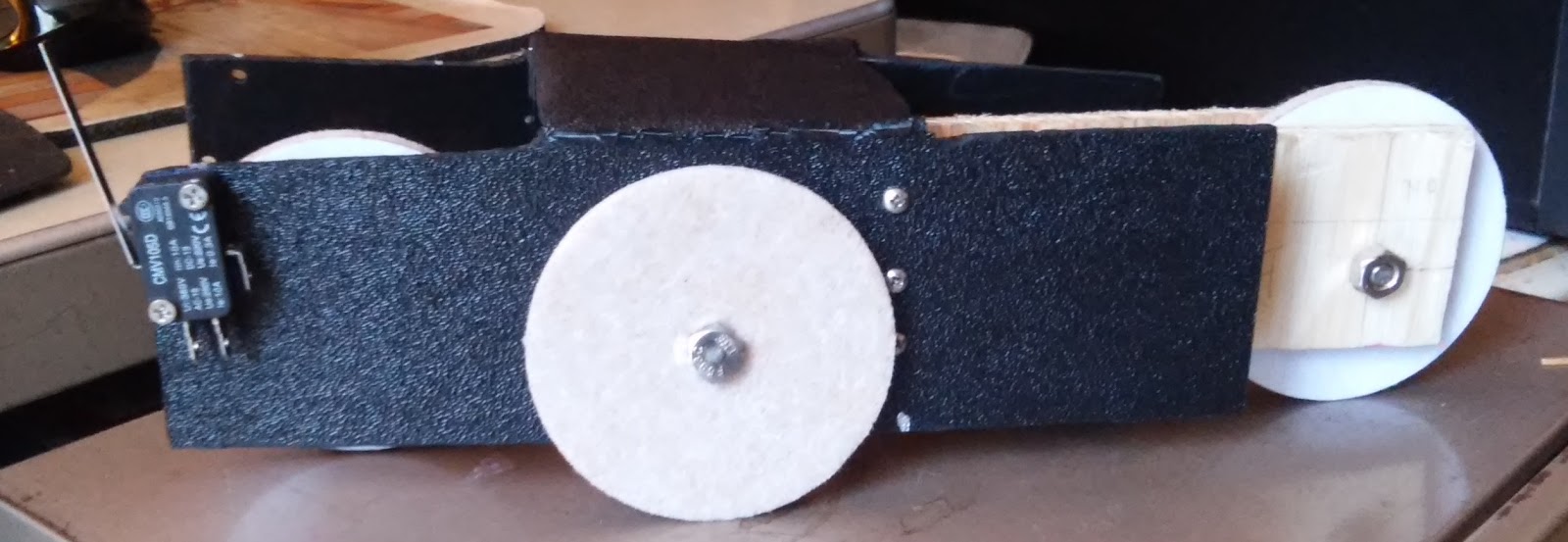
Right view. Note the limit switch on the front.
Front view (driving wheel, motor. limit switch)


Rear view (moveable wheel assembly, hinge)

Left view (motor protruding through hole)


Saturday, August 22, 2015

@MAKE #Electronics Experiment 32: Robot Cart (Part IIA-Better)

3rd attempt at the cart.  Used a hand saw this time, and my handy drill. I marked Xs on the pieces I want to cut out to remind me what I'm doing.

Cart is now fabricted.  You can see some damage from bending the frame, but it will do for now.  I may redo it if I like the final product and want to showcase it.
OK, so I can't follow directions. It's a good thing I bought 10 sheets of ABS, because I have ruined 2 now, and may need another.  I got through my measuring, drilling and cutting, only to see that I pu the cuts on the wrong side.  So, I measured and drilled again...that's the top photo..and took the step to mark the pieces that wanted to cut out.

I made the cuts. used my heat gun to soften the plastic, and bent the sides.  I left the final cuts (removing the short pieces on what would become the top) so I could bend those into a position to cut them.  It was ugly.

I'd like to say that I started on the wrong side on purpose (one side is textured and the other smooth), but it was by mistake. It turned out to be almost OK because I had significant shaping and deburring to do, using my Harbor Freight Dremelish tool.

When I bent the frame back to put the textured side out, there was some damage (see lower photo).  It's usable as-is, so I'm going with it.  If I really like the cart when it's done. I'll redo the frame.

Next:
By some 14" plywood, the hardware (hinge, bolts, nuts, screws), and maybe some 3" disks to use as wheels,  as suggested by James Floyd Kelly.

Thursday, January 29, 2015

@MAKE Electronics Experiment 19 - logic chips (Part I)

There is not much to Experiment 19, but it's still really neat.

This is the first use of logic chips, and Charles is just introducing the concept. In this experiment, we use a 74HC00 quad 2-input NAND chip and a 74HC08 quad 2-input AND chip.  My 08s have not arrived from China yet, so Part I deals with the 00.

Logic chips use Boolean logic, taking False as 0 and True as 1.  Since there are two inputs, the Boolean operation yield an off or on (logic LOW or logic HIGH) condition.

The 00 applies a NAND, or negative and, operation on the two inputs.  This means that it's the opposite of an AND operation, in which both inputs must be true (or on or HIGH) to yield a true (or on or HIGH) output.  The negative of that means that NAND yields a true (or on or HIGH) result unless bioth inputs are true (or on or HIGH).

Here's a truth table (T=true or on or HIGH, F=false or off or LOW):

input1     input2   AND  NAND
  F             F            F          T
  F             T            F          T
  T             F            F          T
  T             T            T          F

In the experiment, we first have to supply 5V, regulated, to the chip.  We take the 9V input (in my case from a Compact Switching Power Supply - Selectable Output 3-12VDC from Adafruit), through a 7805 voltage regulator and 2 capacitors to smooth it out. The output of the 7805 (4.95V by my meter) supplied the chip. Charles calls for a 33uF capacitor, but I only have 22s and 47s, so I used a 47.

The circuit only used one of the 4 gates. 74HC00 is a 14-pin chip.  Pins 1, 4, 9, and 12 are input1. Pints 2, 5, 10, and 13 are input2.  3, 6, 8, and 11 are the outputs from the corresponding inputs. 14 is power and 7 is GND. Gate 1 is pins 1 and 2 with output on pin 3.  All other input pins are tied to GND (LOW), and the other 3 outputs are floating.

The inputs 1 and 2 (pins 1 and 2) are connected to power through a normally open momentary switch., with 10K pull-down resistors connected to GND. Output (pin 3) is connected to a low-current LED, which is connected to a 1K resistor to GND. Each input is LOW unless the button it is connected to is pushed, closing the connection to power and taking it HIGH.

Here's the schematic and breadboard layout:

Figure 4-46
Figure 4-47


Both figures are from Charles Platt, Make: Electronics, First Edition, Maker Media, Inc., 2009, p. 182.

Both inputs are LOW on power up. Pressing a button takes its input HIGH. Referring to the truth table above, we expect the LED will light unless both inputs are HIGH. This is in fact what happens: when the power is connected, the LED is on and stays on unless both buttons are pushed. See the video here.