Showing posts with label robot. Show all posts

Wednesday, April 19, 2017

Fun with Robots, IR Decoding, LED Matrix, etc.

Fig 1: Three experiment--two with the samsung remote on the left, one with the Radio Shack remote on the right--to control a +Adafruit Industries 8x8 Bicolor LED Matrix
I haven't posted in a while because several interests have kept me very busy. This all started withe the +Parallax Board of Education (BOE) Robot kit. I asked for and received on for Christmas a couple of years ago and let it ripen until I was ready.  I decided that it would make a good project to do with my 7-year-old granddaughter when she visits this summer--but first, I should make sure that I can build it without a lot of fumbling. Fumbling is good, but watching me figure out what dumb thing I did is not always interesting to a 7yr-old. I followed the tutorial and learned quite a bit, The last project that I did used infrared for proximity sensing to avoid obstacles. At the same time, +Adafruit Industries, via The Desk of Lady Ada, provided some great information on IR. So, I decided to play and learn further.
Fig 2: +Parallax BOE Bot with 2 IR transmitters aand 2 IR receivers

IR Decoding the Hard Way

Following the +Adafruit Industries tutorial on IR Sensing, I was able to decode only some of the buttons on my Samsung TV Remote (see Figure 1). Using the remote is a 2-step process: first decode the signals send by the buttons, then use the decoded signals in a different sketch that takes action based on the buttons. Using this method (see the Raw IR Decoder and ircommander code on github), I was able to decode some of the buttons and use them in a sketch.  

Quick diversion:  I have had big plans to use a 32x32 LED Matrix that I bought in a parking assistant project that will display faces to convey the emotions evoked by a car getting increasingly closer. I decided to use the 8x8 bicolor matrix and backpack to prove the concept, and use the remote to signal which face to display. Figure 1 shows the initialized yellow face (looks orange to me). So, I needed to follow the tutoral for the matrix and backback library.

I was able to merge code from the bicolor8x8 example code in the Adafruit LED Backpack library with code from the ircommander sketch referenced above. After adding the decoded remote buttons to a newly created library (see the IR Sensor tutorial and the project video cited at the end of this post), I was able to change the face on the matrix based on the remote buttons.

I found both the coding aspect and the operation of the technique to be less than perfect.  Maintaining a separate library with very long sequences of numbers just to test what button  was pressed seems a bit much. In operation, the code seems to reset itself randomly, and only respond to buttons when it feels like. This may be me, and I will investigate, but read on to see a much neater technique.

IR Decoding an Easier Way

After working through the above, I watched Lady Ada work through Chris Young's IRLib2 in one of the Desk of Lady Ada epdisodes cited above.  Chris, aka cyborg5, is a frequent visitor to the Adafruit Show and Tell, and has done a lot of great work (see his blog).  Both the decoding and the processing techniques are simplifies greatly, and his library handles several IR protocols. The IRLIB2 tutorial describes it all very well.  You wind up with one simple code that you supply in a sketch so you can determine what button was pressed--straightforward, and I was able to decode all the buttons with no missed presses. From there it was a matter of simplifying the sketch I wrote earlier to display faces on the LED matrix.  Again, the project video shows all this.

Controlling Motors with IR

Since we started with robots, I thought it would be interesting to control motors with IR.  It was a simple matter to modify the IRLib2 sketch above to direct the continuous rotation servos.  I took code from the BOE-Bot project, and code from the Adafruit_PWMServoDriver library tutorial, and it went smoothly.  The servos in the BOE-Bot are different from the Adafruit ones, so I had to go to the data sheet to see what values to use to get them to move as I wanted. I was able to decode all the buttons on the Samsung remote, and used the arrow keys to simulate moving the robot forward, back, left, and right.

I first did this without the PWM Servo FeatherWing. Because the feather is 3V logic, I needed a level shifter to handle the signals from the board to the servos. That worked, but added a few connections and I used the Arduino servo library as opposed to the Adafruit library which allowed for simpler code.

Another thing I needed to worry about was timer conflicts. I had come across this before, in my Donkey Project, but Chris' tutorial gave a straightforward explanation and solution. The problem is that the servo library uses Timer1 and on the 32u4 Feather IRLib2 does too. It was necessary to go into one of the associated libraries and change one line of code to re-assign the timer.  You'll get better instruction in the tutorial than I can give here.  Again, the project video shows the results.
Controlling 2 FS90R continuous rotation servos from an Adafruit BLE Feather and PWM Servo FeatherWing

Trying a Different Remote

A while back, Radio Shack sold some MAKE project kits, including robotics. During an earlier RS bankruptcy, I acquired a RS remote at a big discount and still had it in inventory, so I decided to try it out. Using the IRLib2 approach to decoding, I found the the protocol was not one of supported ones. A look at the datasheet for the PT2248 chip in the remote revealed that ot used the Toshiba protocol. So, I had to go back to the hard way, and I got that to work.  See the video.

IR Affects the BOE-Bot

Just for grins, I took out the BOE-Bot, let it runon the floor, and chased it with a remote.  The bot's IR retrievers detected the transmissions, and the bot reacted accordingly (moving left or right as if it had detected an obstacle).

Project Video

See the project video on YouTube

Thursday, September 8, 2016

Hopping Robot V2


As mentioned in my last post, I had a couple of updates to pursue.

First, the hot glue was not holding.
Solution: I was using a low-heat version, so I went out and bought a new dual temp version at Home Depot.

Second, the battery holder I had was open, so the batteries fell out.
Solution: I found 5 closed ones on eBay for the same price as one open one at Radio Shack. These hold on carpet and wood but not concrete. This holder has an added advantage in that it has a switch, so I eliminated the slide switch (fewer connections is better).

Third, the motor flopped around the legs as opposed to the legs driving the robot.
Solution: I added a second bolt hot glued to the frame.  It's not perfect, but better.  Next option would be to use narrower legs, to make them lighter.

So, I'm going to declare victory here, and move on to The Mover now that I've got the fabrication down.

Tuesday, August 30, 2016

Hopping Robot: How I made one


I found this very interesting video, and I will give the author +sauravchakra all the credit for the idea and the demonstration.

However, I would not call this a tutorial--it's a 4+ minute demo of the operation some information on the process. So, I decided to take it to he next step. First, here's all of what I used in the project. Others may add their own ideas, but this is a start, and more than was in the video.

See notes under "Step 5 -Hop!" for planned improvements.

Parts

aluminum: 2 pieces 3cmX1cm (I used scrap from a discarded light fixture)  Author says to drill a 2mm hole 5mm from edge. Since I used bigger screws, I used a 1/8" drill bit (~3mm)
batteries:  3 AAA
battery holder: 3XAAA; see Radio Shack (See note under step 5)
carriage bolt: 1 2" bolt--got it a local hardware store
DC Gear Motor: Only spec is 100RPM. It's a 90 degree shaft,
and we can intuit 4.5V from the power used.  See Jameco
I found one on Amazon for less but shipping takes over a month.
metal rod: 1" long, diameter small enought to fit the wheel, below.
I used parts from a printer tear-down.
plastic: you'll need to cut a piece 5" X 1". I had these around from Amazon.
plastic wheel : 1, small enough to fit in plastic and be held by metal rod above; I used parts from printer teardown, author used a bead
PVC pipe:  need 1 piece 1/2" wide.  Tutorial says 7 cm pipe = ~2.75in--I used 3.5in (outside dimension), from scrap.  Find it at a local hardware store or Home Depot
screws/nuts: author calls for tiny metric screws (like M1.5). I tried that, and my fingers are to fat and clumsy to get that done. I used some 1/2" 4-40 machine screws and nuts that I had bought from a local hardware store
slide switch  (SPDT):  This could be SPST, but this is what author used and also what I had, from Adafruit

Tools and Supplies

Coping Saw: to cut plastic, bought at local hardware store
Files: for deburring metal and plastic--I have this set from Harbor Freight
Hack Saw: for cutting metal and PVC, sourced locally
Heat Gun: to soften plastic for bending and for heat shrink;  inexpensive at Harbor Freight
Heat Shrink Tubing: to insulate soldered wires (batteries/motor/switch), from Radio Shack, Adafruit, et al.
Hot Glue Gun: to attach various components; Home Depot has this one
Snips: to trim metal and plastic--sourced locally
Soldering Tools:solder battery/motor/switch connections, from Radio Shack, Adafruit, et al.
Vise: I make great use of my bench vise like this Craftsman
Wire Strippers: for cutting and stripping the motor and battery wires to prepare for soldering--sourced locally

Assembly

The photo above shows the parts ready for assembly.  Clockwise from upper left:
  1. Slide switch
  2. 2" carriage bolt
  3. DC Gear Motor with aluminum pieces attached to rotating arms
  4. 2 halves of a 1/2" slice of PVC pipe, for the legs
  5. battery holder
  6. piece of ABS plastic, cut to size, bent at the 1/4 with indentation for the wheel, 1/16" holes for the switch leads, and a 1/8" hole for the battery wires
  7. I left the rod and wheel out of the photo. See Step 2.
The process

Step 1 - fabricate the parts
The PVC pipe, the plastic, and the aluminum pieces all needed to be cut out.  
PVC: I found a piece of 3.5" PVC pipe, cut off a half inch slice, then cut that in half
Plastic:  a had some sheets of 1/8" thick ABS, and in fact had plenty of scrap from other projects, so I took a small piece and cut it to size with a coping saw. Then I measured one quarter of the length, drew a line, hit that area with the heat gun, then put it in the vise and bent it to a 90 degree angle. Then I cut out about a 3/4" section, 3/8" high out of the bottom of the bent section.  That's where the wheel will go. I needed a hole for the battery wires and 3 hole for the switch pins, so I drilled those.
Aluminum: I had replaced a failed under-counter fluorescent light fixture and kept the old housing for scrap.  I cut out two 3cm by 1cm pieces (really about 1.25" X .5" ). I tried the small M1.5 screws but my fingers just would not cooperate, so instead of a 2cm hole I drilled a 1/8" hole to accommodate 4-40 machine screws.

legs hot glued to aluminum
Step 2 - attach the legs
one leg with hot glue treads
  1. Drill 1/8" holes in the rotating arms of the motor (make sure you put them on the same side so the metal pieces are oriented in the same direction--i.e., not one horizontal and the other vertical). My drill doesn't do metal too well, so I used a hammer and nail to complete the hole
  2. Fasten the aluminum pieces to the arms with 3/8" 4-40 screws and nuts
  3. Hot glue the PVC pieces, with the convex side facing the rear (opposite from the rotating end).
  4. Add lines of hot glue about every 1/2" along the outside of the PVC for traction.
Step3 - populate the frame
rod, wheel, and slot in frame
wheel hot glued to frame


  1. Put the rod through the wheel and hot glue it to the open area in the frame (making sure that the wheel clears the bottom of the frame and turns freely)
  2. Hot glue the switch to the frame, with the pins through the 3 holes
  3. Hot glue the battery holder to the frame and thread the wires through the 1/8" hole
  4. Hot glue the motor+legs to the frame--check the photos to be sure everything is facing in the right direction
Step4 - wire it up
  1. First connect the red wires and black wires from the motor and batteries to each other.  The legs should turn clockwise. If not, reverse the wires.
  2. With the polarity verified, start trimming and soldering.
  3. After wiring and testing, hot glue the 2" carriage bolt in place for stability


Step 5 - Hop!

It's done and it works, but I need to make some improvements.

  1. I couldn't find my hot glue gun, so I borrowed a low-temp one from my wife.  I'm blaming that for the fact that the legs come off at times, so I'm going to find mine or by a real one, and re-fasten the legs
  2. The open battery holder does not secure the batteries and the tend to fall out.  I have enclosed ones on order from eBay, but ti will take a while
  3. The PVC may be too heavy, because the legs what to stay still while the motor spins.  It's still amusing, but not as designed.  I may try thinner legs (e,g., 3/8" slices of PVC instead of 1/2")

Monday, September 7, 2015

@Make: Electronics Experiment 32 Robot Cart - Together and Working, need to pretty it up

This took WAY too long, due to my fumbling.  Earlier posts and videos showed it working on a breadboard,  I needed to solder the components and circuit to a Perma-Proto Board, then connect the wires from the cart (motor + and -,  switches NO and GND).

Here's a top view of the working product:

Note the 4-pin connector I used to connect the 4 wires mentioned above through a hole in the Altoids tin to the circuit board.  That allows me to unplug the components on the cart to work on the circuit board if (WHEN) I need to, What look like stray wires are stubs for testing.  I'll reduce those during cleanup. The switched 9V battery holder is riding in the cover now.  I'll attach it to  the top of the tin with Velcro after I close it up.  I think I need a new Altoids tin--I kind of butchered this one making holes.

I added the rubber band around the driving wheel after the video for traction. It couldn't run on the hardwood floor without it.

Here's the video.

Stupid Soldering Tricks

There were reasons why it too so long.  I used 3 Perma-Protos. I would get it working, then something would go haywire.  I had a short someplace. I lost about a day fussing wit the power supply (see the right side of the photo above). I had been using 10uf and 1uf capacitors, but looked at the LM7805 datasheet and saw that the sample uses 33uf and ,1uf (same as in the book, p 182).  DUH. It said .33...so I chased that for a while, buit ibn the right components and still had a short.

I could not see anything wrong, so I decided to do a new board.  Worked OK for a while, but eventually wound up with another short.  I was ready to give up and just use a breadboard, but decided to try one more board.  After fussing with all kind of connections, I moved the 555 and reconnected everything pin by pin.  Of course, I started with pin 1 and the problem was on pin 8.  I had decided to use a 3-pin female header across pins 7-8 and the next row to connect the 33uf capacitor, so I could swap other values in and out to adjust the backup time (since I removed the pot).
I must have had a cross connection due to sloppy soldering under the header, because when I soldered in the cap direcly I had no  problem.

Now I was in business, but I had a couple of recurring problems.  I cleaned up some stray solder and it appeared to be OK.  It took a week, but I did it.

Finishing the Fabrication

I had everything working, connecting the cart to the circuit board with alligator leads.  I cut a 4-pin I2C cable in half to use as a connector to the cart, with the cut half to be soldered to the circuit board. I soldered the motor and switch wires to a strip of 4 extra long male header pins, and plugged that into the I2C connector. I tested the circuit after soldering each connection, and used head shrink to insulate the pins. The I soldered all the connections on the motor and switches.

What I need to do

  1. Screw the Perma-Proto to the standoffs and close the cover of the Altoids tin
  2. Velcro the 9V battery holder to the Altoids tin
  3. Use threadlocker on the wheels to keep them from wobbling
  4. Maybe screw the drive wheel to the motor (I would need to remove the motor to do that)
  5. Tidy up all the wires
  6. Put some WD-40 on the hinge so the tail moves more smoothly


Thursday, August 27, 2015

@MAKE #Electronics Experiment 32: Robot Cart (Part III - Cart is together)

The saga continues...

I put the pieces of the cart together as shown here:
I attached the hinge to the body only to expand the pilot holes to make it easier when I put the movable wheel assembly together (see upper right).  The wheel at the lower right has the mounting wheel for the motor ready to go.

Next step was the wheel assembly.  I needed 1" #6 bolts to put the 3 pieces together (each piece is 1/4").  Once I got it together I realized that it was upside down (the holes for the axle needed to be on the bottom), so took it all apart and reassembled.

Next was the driving wheel. The pre-drilled holes in the mounting wheel were not big enough for any screws I had or could get quickly, so I reamed them and used #4 sheet metal screws (needed 1/2"--another shopping trip).  Pan head screws won't do because the wheel needs to clear the motor. Even with flat-head screws I had to file down a small plastic cylinder on the motor, which has no use that I can discern.

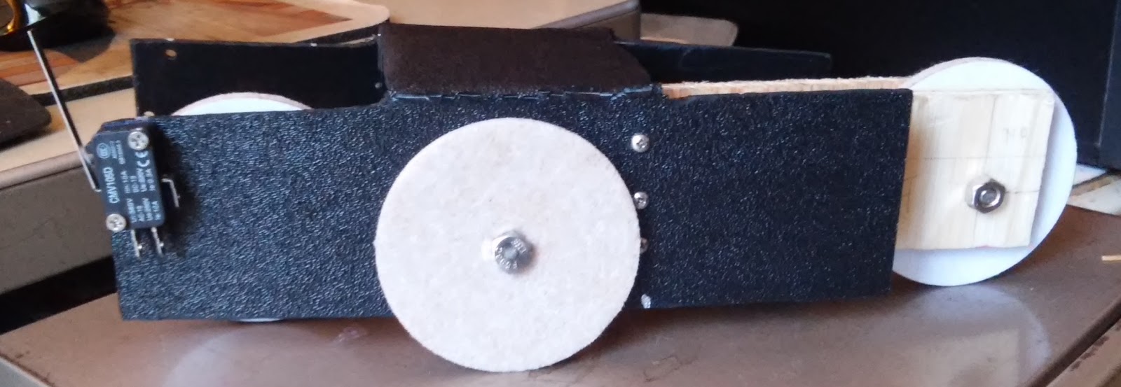
Now I was ready to mount the motor. I was clueless here, but I thought ahead enough to buy a mounting bracket, which attaches to the motor with a #4 machine screw (again, 1/2" flat-head). I measured the cylindrical piece to the motor--it's 3/4". I drilled a 3/4" hole in the ABS side (3/4" from the bottom like the other wheels, and over enough so that the wheel did not extend beyond the front of the body--2.25" in). I had to file the hole to get the motor through it, but it's in and stays put. The bracket doesn't do much, but if I need to secure the motor later on, I can screw it to a piece of plywood that I secure to the frame.

The motor is a Solarbotics GM2 Offset Shaft Gear Motor. I used a Solarbotics GMW mounting wheel, and GMB28 Mounting Bracket.

Next was the limit switches.  They need to be in the front with the sensors out so that when they hit something the switch will activate the timer sequence and flop the relay for 5 seconds, reversing the motor. (See my post, including a video, on the circuit.) I drilled the holes (1/8") on both sides but only mounted one, using 3/4" #4 machine screws and nuts.  I'm keeping the other connected to the breadboard circuit for the final pre-completion test.

Next Steps:

  • test the circuit again
  • construct the circuit on an +Adafruit Industries Perma Proto Board and mount it on standoffs in an Altoids Tin with insulation on the bottom
  • test and rework as necessary
  • solder everything up and go


Here's what it looks like at this point:
Right view. Note the limit switch on the front.
Front view (driving wheel, motor. limit switch)


Rear view (moveable wheel assembly, hinge)

Left view (motor protruding through hole)


Saturday, August 22, 2015

@MAKE #Electronics Experiment 32: Robot Cart (Part IIA-Better)

3rd attempt at the cart.  Used a hand saw this time, and my handy drill. I marked Xs on the pieces I want to cut out to remind me what I'm doing.

Cart is now fabricted.  You can see some damage from bending the frame, but it will do for now.  I may redo it if I like the final product and want to showcase it.
OK, so I can't follow directions. It's a good thing I bought 10 sheets of ABS, because I have ruined 2 now, and may need another.  I got through my measuring, drilling and cutting, only to see that I pu the cuts on the wrong side.  So, I measured and drilled again...that's the top photo..and took the step to mark the pieces that wanted to cut out.

I made the cuts. used my heat gun to soften the plastic, and bent the sides.  I left the final cuts (removing the short pieces on what would become the top) so I could bend those into a position to cut them.  It was ugly.

I'd like to say that I started on the wrong side on purpose (one side is textured and the other smooth), but it was by mistake. It turned out to be almost OK because I had significant shaping and deburring to do, using my Harbor Freight Dremelish tool.

When I bent the frame back to put the textured side out, there was some damage (see lower photo).  It's usable as-is, so I'm going with it.  If I really like the cart when it's done. I'll redo the frame.

Next:
By some 14" plywood, the hardware (hinge, bolts, nuts, screws), and maybe some 3" disks to use as wheels,  as suggested by James Floyd Kelly.

Friday, August 21, 2015

@MAKE #Electronics Experiment 32: Robot Cart (Part II)


So, carpentry and fabrication are not my strong suits. Evidently I'm not real strong on following directions, either. Anyway, this is pass one, and I'll keep at it.

The good news:  I proved that I can use the 12"x12"x1/8" sheets of ABS (that I bought from Amazon about a year a go thinking they's come in handy) for the main cart body.  They're not thick enough to screw into, so I'll add 1/4" plywood, or maybe see if I can find 1/4" ABS.  I was able to cut the sheet to 9"x8", drill holes for rounding corners, then cut the rest, and use my heat gun to soften it for bending into shape See Fig. 5-92 on p. 275.

Problems:
  1. I used the wrong saw. That's why the cuts look ugly.  I knew that, but I bought a reciprocating saw at Harbor Freight and have been dying to use it.  I'm going to a hand saw, maybe a coping saw. 
  2. I drilled 3 of the holes in the wrong place. The idea is to have 1/2" diameter holes to round the 4 corners of the cut ABS, but you need to drill the holes in the inside of the cut, not the outside (that's why you see some holes that don't appear to be random--they are just wrong).
Other than that it's great.  I'm ready for pass two, and I learned a lot.

Tuesday, August 18, 2015

@MAKE #Electronics Experiment 32: Robot Cart

I'm ready to start on this. First step was to gather the materials.  The parts list on page 268 is incomplete, although on p. 276 there's a "you will also need..." See the schematic on p.277 and this blog post by +James Floyd Kelly  (it's on experiment 31, but references shopping for 32). The 50K potentiometer shown in the schematic controls the time the motor runs in reverse before going forward again.
Make: Electronics by Charles Platt, Figure 5-98. p.277 (in the edition I have)

Also, the erratum on p. 277 mentions adding a diode or transistor. I'm going to try a diode (handsonelectronics says diode).

I found that my DPDT relays on hand are not appropriate. Some are latching relays bought for experiment 20, and the other was 12V, so I ordered two 5V DPDT non-latching relays from Amazon.

Charles spends a great deal of time on fabrication and not much on the circuit.  Since I care more about the circuit, and there are some issues with it, I'm going to build that first. I'm going to try to use plastic for fabrication. I have some 12"X12" pieces of ABS, and the shell of a multi-function printer that I tore-down.

Here's the concept:
When switched on, the cart moves forward until one of the microswitches hits something, it cuts power to 555 Trigger Pin 2, causing the the Output Pin 3 to pulse the relay, which then flops, reversing voltage to the motor, which reverses. The timer cycle (determined by 555 Threshold Pin 6 and Discharge Pin 7 as powered by the capacitor/resistor combination along with the Pot). When the cycle ends, the Output Pin 3 goes low and the relay flops back, causing the motor to reverse again (making it go forward).

The time it reverses starts at ~5 seconds (47uf cap*100000Ohm resistor = 47//1000000*100000 = 4.7). The Pot did not make much difference, if any. I thought it did, but it turned out that I had unhooked the 100K resistor. DUH.

I had other DUH moments in this, but I was helped immeasurably but people running into the same problems I did, particularly +James Floyd Kelly .  Thank you James. First, I bought a 5V gearmotor from robotshop .com. I fussed around for way too long trying to figure out how to wire it--then I noticed the two copper tabs on the neck.  Second, I was getting weird buzzing from the relay, and the motor was not reversing. I remember the symptoms from James' blog. My relay had different pinouts from the schematic. There are 8 pins. If you number them 1-8 starting with 1 at upper left and go counter clock-wise, I needed to switch pins 2 and 3 on one side and 7 and 6 on the other.  I could not find a datasheet for this relay, but I had a similar issue once before with another DPDT relay, so I guessed.

Third problem was the diode,  The motor would not reverse, but fortunately I had seen this before (thanks James), so I added the diode across pins 1 and 8 of the relay with the cathode towards pin 8.

I also struggled with wiring the switches.  I tested it with just the switches, power supply, and a meter, and came up with:
555 Trigger Pin 2  to switch1 NO prong, connected to switch 2 NO
Both NC Prongs connected to GND
Both COM prongs (on the side--at least on mine) connected to GND

If neither switch is pressed, current is flowing to the trigger pin through the 10K pull-up resistor making it high and thus the output pin is low. When either switch is pressed, the trigger pin goes low, making the output pin high, and flopping the relay and reversing then motor.  The output pin stays high until the 47uf capacitor dishcarges (4.7sec) to the threshold pin, making it high and setting the output pin back to low, flopping the relay back and the moving the motor in the original direction.

It works.  Here's the video.