Monday, September 7, 2015

@Make: Electronics Experiment 32 Robot Cart - Together and Working, need to pretty it up

This took WAY too long, due to my fumbling.  Earlier posts and videos showed it working on a breadboard,  I needed to solder the components and circuit to a Perma-Proto Board, then connect the wires from the cart (motor + and -,  switches NO and GND).

Here's a top view of the working product:

Note the 4-pin connector I used to connect the 4 wires mentioned above through a hole in the Altoids tin to the circuit board.  That allows me to unplug the components on the cart to work on the circuit board if (WHEN) I need to, What look like stray wires are stubs for testing.  I'll reduce those during cleanup. The switched 9V battery holder is riding in the cover now.  I'll attach it to  the top of the tin with Velcro after I close it up.  I think I need a new Altoids tin--I kind of butchered this one making holes.

I added the rubber band around the driving wheel after the video for traction. It couldn't run on the hardwood floor without it.

Here's the video.

Stupid Soldering Tricks

There were reasons why it too so long.  I used 3 Perma-Protos. I would get it working, then something would go haywire.  I had a short someplace. I lost about a day fussing wit the power supply (see the right side of the photo above). I had been using 10uf and 1uf capacitors, but looked at the LM7805 datasheet and saw that the sample uses 33uf and ,1uf (same as in the book, p 182).  DUH. It said .33...so I chased that for a while, buit ibn the right components and still had a short.

I could not see anything wrong, so I decided to do a new board.  Worked OK for a while, but eventually wound up with another short.  I was ready to give up and just use a breadboard, but decided to try one more board.  After fussing with all kind of connections, I moved the 555 and reconnected everything pin by pin.  Of course, I started with pin 1 and the problem was on pin 8.  I had decided to use a 3-pin female header across pins 7-8 and the next row to connect the 33uf capacitor, so I could swap other values in and out to adjust the backup time (since I removed the pot).
I must have had a cross connection due to sloppy soldering under the header, because when I soldered in the cap direcly I had no  problem.

Now I was in business, but I had a couple of recurring problems.  I cleaned up some stray solder and it appeared to be OK.  It took a week, but I did it.

Finishing the Fabrication

I had everything working, connecting the cart to the circuit board with alligator leads.  I cut a 4-pin I2C cable in half to use as a connector to the cart, with the cut half to be soldered to the circuit board. I soldered the motor and switch wires to a strip of 4 extra long male header pins, and plugged that into the I2C connector. I tested the circuit after soldering each connection, and used head shrink to insulate the pins. The I soldered all the connections on the motor and switches.

What I need to do

  1. Screw the Perma-Proto to the standoffs and close the cover of the Altoids tin
  2. Velcro the 9V battery holder to the Altoids tin
  3. Use threadlocker on the wheels to keep them from wobbling
  4. Maybe screw the drive wheel to the motor (I would need to remove the motor to do that)
  5. Tidy up all the wires
  6. Put some WD-40 on the hinge so the tail moves more smoothly


Thursday, August 27, 2015

@MAKE #Electronics Experiment 32: Robot Cart (Part III - Cart is together)

The saga continues...

I put the pieces of the cart together as shown here:
I attached the hinge to the body only to expand the pilot holes to make it easier when I put the movable wheel assembly together (see upper right).  The wheel at the lower right has the mounting wheel for the motor ready to go.

Next step was the wheel assembly.  I needed 1" #6 bolts to put the 3 pieces together (each piece is 1/4").  Once I got it together I realized that it was upside down (the holes for the axle needed to be on the bottom), so took it all apart and reassembled.

Next was the driving wheel. The pre-drilled holes in the mounting wheel were not big enough for any screws I had or could get quickly, so I reamed them and used #4 sheet metal screws (needed 1/2"--another shopping trip).  Pan head screws won't do because the wheel needs to clear the motor. Even with flat-head screws I had to file down a small plastic cylinder on the motor, which has no use that I can discern.

Now I was ready to mount the motor. I was clueless here, but I thought ahead enough to buy a mounting bracket, which attaches to the motor with a #4 machine screw (again, 1/2" flat-head). I measured the cylindrical piece to the motor--it's 3/4". I drilled a 3/4" hole in the ABS side (3/4" from the bottom like the other wheels, and over enough so that the wheel did not extend beyond the front of the body--2.25" in). I had to file the hole to get the motor through it, but it's in and stays put. The bracket doesn't do much, but if I need to secure the motor later on, I can screw it to a piece of plywood that I secure to the frame.

The motor is a Solarbotics GM2 Offset Shaft Gear Motor. I used a Solarbotics GMW mounting wheel, and GMB28 Mounting Bracket.

Next was the limit switches.  They need to be in the front with the sensors out so that when they hit something the switch will activate the timer sequence and flop the relay for 5 seconds, reversing the motor. (See my post, including a video, on the circuit.) I drilled the holes (1/8") on both sides but only mounted one, using 3/4" #4 machine screws and nuts.  I'm keeping the other connected to the breadboard circuit for the final pre-completion test.

Next Steps:

  • test the circuit again
  • construct the circuit on an +Adafruit Industries Perma Proto Board and mount it on standoffs in an Altoids Tin with insulation on the bottom
  • test and rework as necessary
  • solder everything up and go


Here's what it looks like at this point:
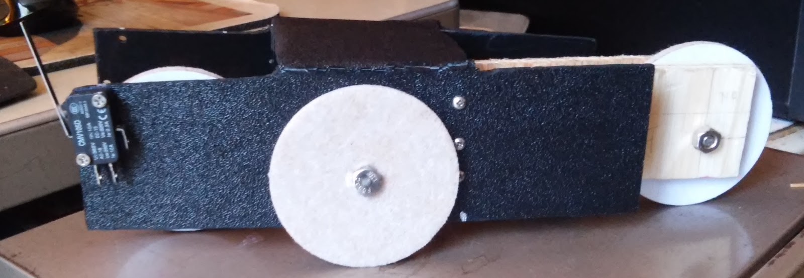
Right view. Note the limit switch on the front.
Front view (driving wheel, motor. limit switch)


Rear view (moveable wheel assembly, hinge)

Left view (motor protruding through hole)


Monday, August 24, 2015

+Adafruit Neopixel Tiara on an Actual Tiara- Almost Built

Design change:  I have ruled out the CR1220's (not enough battery life, too hard to change), and the CR2032's (too bulky). +Becky Stern  was trying to push me towards a LiPo battery, and I resisted...but finally realized she is right. The 100mAh version is small and the right size to fit the tiara.

I sewed eacghneopixel to the tiara using silver
thread.  Here's the first, ready to go..
The "V2" on the back side happens to be on the
"data-in" pin, so I started there with each one.
Here's the tiara with pixels shown. I'm still have to clean up the stray threads.
The sewing took me an afternoon (not an expert), but I got it done and it's not too ugly.

Next I soldered the neopixels together (+ to +, - to -, DO to DI), then connected the Gemma to the first neopixel for a test, using alligator test leads--see the video. The soldering took a couple of hours. For each wire, I used calipers to measure the distance between neopixel pads, stripped 14", marked the desired length of unstripped wire (from the calipers), cut the wire 1/4" beyond, and stripped 1/4" off that end.

I did the data bus first, and used stranded wire.  That turned out to be a huge pain--it's too flexible and the ends are hard to deal with.  I switched to 22awg solid core wire for the power and GND busses. Much easier.  I will go back to stranded when I wire the Gemma, because I will need the flexibility.

Also, I discovered (or remembered, not sure which) that Gemma has an on-off switch on board.  That simplifies this circuit (I don't need to add a switch).

Next:

  • trim stray threads and wire to clean up as much as possible
  • re-sew at least one of the neopixels (some threads got burned during soldering)
  • secure and insulate the threads and wires with nail polish
  • add the 100mAh battery
  • glue the Gemma to the tiara
  • solder the Gemma connections to the circuit, attach the battery to the tiara.


Parts list:

Saturday, August 22, 2015

+adafruit Neoplxel Tiara on an actual tiara

This is an ongoing saga. I got the idea to put the neopixel tiara on an actual tiara for my granddaughter's Nursery School graduation in June. I could not find a suitable plastic tiara, and the the metal one I built needed so much insulation that it was ugly. Also, the Gemma and battery back make it unwieldy for a 5-year-old. Here's a video:


I found some plastic tiara's that are not great but the may do the rick. Here's a photo comparing the two:

I took the metal one down for her graduation, and I brought my spare, unwired.  She wore the plain tiara all day every day, but was not impressed by my circuit--as I said, ugly and unwieldy.So, back to the workshop. I'm planning something for her 6th Birthday this Fall.

I got lots of help from Becky Stern of Adafruit, on air on Wearable Wednesday, and on the Adafruit Support Forums. The code is the same as my Twinkling Daffodils, except that I use a different pin on the Gemma than I did on the Trinket for the Daffodils (convenience).

I took out another Gemma and programmed it.  BTW, since I last worked on this the Arduino IDE wend from 1.6.3 to 1.6.5.  I had 1.6.4 installed, with the Adafruit boards added in.  After I upgraded to Windows 10 last week, I upgraded the IDE to 1.6.5.  It was a completely painless upgrade.  I didn't have to reload any of the Adafruit stuff or any drivers, and Windows 10 did not interfere at all.

I plan to glue the Gemma behind the middle of the tiara, sew or glue the 6 neopixels in the loops (as in the metal one), and glue the battery pack to the front of the comb.  I can try CR1220s, but they will provide 40mAh.  With 20A for the Gemma and 20 for the neopixels (varyung colors and brightness and not on at the same time), they might last an hour.  (Thanks to Becky's tutorial on batteries.) The problem is that it's hard to change them.  I may have to glue a CR2032 battery holder, or maybe use the sewable holders.

Anyway, I have a fun project to work on while I'm doing the Robot Cart at the same time...and, Halloween is coming!

@MAKE #Electronics Experiment 32: Robot Cart (Part IIA-Better)

3rd attempt at the cart.  Used a hand saw this time, and my handy drill. I marked Xs on the pieces I want to cut out to remind me what I'm doing.

Cart is now fabricted.  You can see some damage from bending the frame, but it will do for now.  I may redo it if I like the final product and want to showcase it.
OK, so I can't follow directions. It's a good thing I bought 10 sheets of ABS, because I have ruined 2 now, and may need another.  I got through my measuring, drilling and cutting, only to see that I pu the cuts on the wrong side.  So, I measured and drilled again...that's the top photo..and took the step to mark the pieces that wanted to cut out.

I made the cuts. used my heat gun to soften the plastic, and bent the sides.  I left the final cuts (removing the short pieces on what would become the top) so I could bend those into a position to cut them.  It was ugly.

I'd like to say that I started on the wrong side on purpose (one side is textured and the other smooth), but it was by mistake. It turned out to be almost OK because I had significant shaping and deburring to do, using my Harbor Freight Dremelish tool.

When I bent the frame back to put the textured side out, there was some damage (see lower photo).  It's usable as-is, so I'm going with it.  If I really like the cart when it's done. I'll redo the frame.

Next:
By some 14" plywood, the hardware (hinge, bolts, nuts, screws), and maybe some 3" disks to use as wheels,  as suggested by James Floyd Kelly.

Friday, August 21, 2015

@MAKE #Electronics Experiment 32: Robot Cart (Part II)


So, carpentry and fabrication are not my strong suits. Evidently I'm not real strong on following directions, either. Anyway, this is pass one, and I'll keep at it.

The good news:  I proved that I can use the 12"x12"x1/8" sheets of ABS (that I bought from Amazon about a year a go thinking they's come in handy) for the main cart body.  They're not thick enough to screw into, so I'll add 1/4" plywood, or maybe see if I can find 1/4" ABS.  I was able to cut the sheet to 9"x8", drill holes for rounding corners, then cut the rest, and use my heat gun to soften it for bending into shape See Fig. 5-92 on p. 275.

Problems:
  1. I used the wrong saw. That's why the cuts look ugly.  I knew that, but I bought a reciprocating saw at Harbor Freight and have been dying to use it.  I'm going to a hand saw, maybe a coping saw. 
  2. I drilled 3 of the holes in the wrong place. The idea is to have 1/2" diameter holes to round the 4 corners of the cut ABS, but you need to drill the holes in the inside of the cut, not the outside (that's why you see some holes that don't appear to be random--they are just wrong).
Other than that it's great.  I'm ready for pass two, and I learned a lot.

Tuesday, August 18, 2015

@MAKE #Electronics Experiment 32: Robot Cart

I'm ready to start on this. First step was to gather the materials.  The parts list on page 268 is incomplete, although on p. 276 there's a "you will also need..." See the schematic on p.277 and this blog post by +James Floyd Kelly  (it's on experiment 31, but references shopping for 32). The 50K potentiometer shown in the schematic controls the time the motor runs in reverse before going forward again.
Make: Electronics by Charles Platt, Figure 5-98. p.277 (in the edition I have)

Also, the erratum on p. 277 mentions adding a diode or transistor. I'm going to try a diode (handsonelectronics says diode).

I found that my DPDT relays on hand are not appropriate. Some are latching relays bought for experiment 20, and the other was 12V, so I ordered two 5V DPDT non-latching relays from Amazon.

Charles spends a great deal of time on fabrication and not much on the circuit.  Since I care more about the circuit, and there are some issues with it, I'm going to build that first. I'm going to try to use plastic for fabrication. I have some 12"X12" pieces of ABS, and the shell of a multi-function printer that I tore-down.

Here's the concept:
When switched on, the cart moves forward until one of the microswitches hits something, it cuts power to 555 Trigger Pin 2, causing the the Output Pin 3 to pulse the relay, which then flops, reversing voltage to the motor, which reverses. The timer cycle (determined by 555 Threshold Pin 6 and Discharge Pin 7 as powered by the capacitor/resistor combination along with the Pot). When the cycle ends, the Output Pin 3 goes low and the relay flops back, causing the motor to reverse again (making it go forward).

The time it reverses starts at ~5 seconds (47uf cap*100000Ohm resistor = 47//1000000*100000 = 4.7). The Pot did not make much difference, if any. I thought it did, but it turned out that I had unhooked the 100K resistor. DUH.

I had other DUH moments in this, but I was helped immeasurably but people running into the same problems I did, particularly +James Floyd Kelly .  Thank you James. First, I bought a 5V gearmotor from robotshop .com. I fussed around for way too long trying to figure out how to wire it--then I noticed the two copper tabs on the neck.  Second, I was getting weird buzzing from the relay, and the motor was not reversing. I remember the symptoms from James' blog. My relay had different pinouts from the schematic. There are 8 pins. If you number them 1-8 starting with 1 at upper left and go counter clock-wise, I needed to switch pins 2 and 3 on one side and 7 and 6 on the other.  I could not find a datasheet for this relay, but I had a similar issue once before with another DPDT relay, so I guessed.

Third problem was the diode,  The motor would not reverse, but fortunately I had seen this before (thanks James), so I added the diode across pins 1 and 8 of the relay with the cathode towards pin 8.

I also struggled with wiring the switches.  I tested it with just the switches, power supply, and a meter, and came up with:
555 Trigger Pin 2  to switch1 NO prong, connected to switch 2 NO
Both NC Prongs connected to GND
Both COM prongs (on the side--at least on mine) connected to GND

If neither switch is pressed, current is flowing to the trigger pin through the 10K pull-up resistor making it high and thus the output pin is low. When either switch is pressed, the trigger pin goes low, making the output pin high, and flopping the relay and reversing then motor.  The output pin stays high until the 47uf capacitor dishcarges (4.7sec) to the threshold pin, making it high and setting the output pin back to low, flopping the relay back and the moving the motor in the original direction.

It works.  Here's the video.